Technical Article
VIGA vs EIGA Gas Atomization: Process & Applications
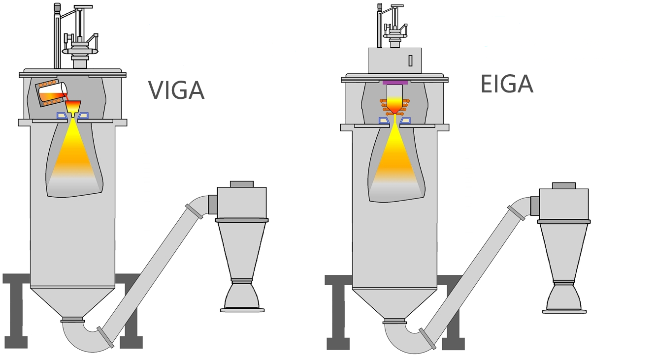
VIGA and EIGA are inert gas atomization processes that convert molten metal into spherical powder, but they use different melting and feeding methods. Vacuum induction melting inert gas atomization (VIGA) melts charge material in a crucible before pouring it through a delivery system. Electrode induction melting gas atomization (EIGA) melts the end of a pre-alloyed bar without a crucible. VIGA provides broader feedstock and alloy-adjustment flexibility; EIGA minimizes refractory contact and is often selected for reactive or high-purity alloys.
The practical choice is not simply “low melting point versus high melting point.” Alloy reactivity, acceptable inclusion level, electrode availability, batch size, melt-stream stability, nozzle geometry, target particle-size distribution, and operating cost all matter. This guide explains both processes, compares their engineering trade-offs, and shows where crucible and atomizing-nozzle materials enter the decision.
Article Contents
- VIGA vs EIGA at a glance
- How the VIGA process works
- How the EIGA process works
- Powder quality and process variables
- How to select VIGA or EIGA
- Crucible and nozzle selection
- Common operating problems
VIGA vs EIGA Gas Atomization at a Glance
The central difference is how the alloy is melted and delivered to the atomization zone:
| Decision factor | VIGA | EIGA |
|---|---|---|
| Full process name | Vacuum induction melting inert gas atomization | Electrode induction melting gas atomization |
| Melting method | Charge melted in a crucible under vacuum or inert gas | End of a rotating or vertically fed bar melted by induction |
| Feedstock | Pieces, ingots, revert, or pre-alloyed charge | Dimensionally controlled, pre-alloyed electrode bar |
| Composition adjustment | Possible during crucible melting and homogenization | Composition is largely fixed by the electrode |
| Refractory contact | Crucible, tundish, or delivery components may contact the melt | Crucible-free melting reduces this contamination path |
| Typical alloy fit | Fe-, Ni-, Co-, Cu-, Al-based and many other melt-compatible alloys | Reactive, refractory, or purity-sensitive alloys such as Ti, Nb, Zr, and Ta |
| Primary control challenge | Crucible compatibility, pouring stability, and nozzle clogging | Stable electrode melting, droplet formation, and feed continuity |
| Scale and productivity | Well suited to flexible batch sizes and high-volume production | Scale depends on electrode diameter, length, melting power, and feed system |
Use process limits as equipment-specific data—not as universal VIGA or EIGA boundaries.
How the VIGA Atomization Process Works
In VIGA, raw materials are induction-melted in a crucible under vacuum or a controlled inert atmosphere. The melt can be held for homogenization and chemistry adjustment before it is poured through a tundish or delivery tube. A high-velocity annular gas jet then breaks the liquid stream into droplets. The droplets cool during flight and are collected as metal powder.
- Charge and evacuate: Load the alloy charge, close the melting chamber, and establish the required vacuum or inert atmosphere.
- Melt and condition: Induction heating melts the charge; temperature, composition, and homogeneity are stabilized.
- Transfer the melt: The crucible is tilted or drained into a tundish and delivery system.
- Atomize: Argon, nitrogen, or another qualified inert gas accelerates through the nozzle and breaks the melt stream into droplets.
- Solidify and classify: Droplets solidify in the tower; powder is collected, sieved, and classified into usable size fractions.
VIGA is attractive when the producer needs charge flexibility, in-melt alloy adjustment, scalable batch production, or powders based on steels, nickel alloys, cobalt alloys, copper alloys, and other materials compatible with the selected refractory system. Its defining risk is melt contact with the crucible and delivery components. Chemical attack, erosion, thermal shock, or poor wetting behavior can introduce inclusions or destabilize the pour.
How the EIGA Atomization Process Works
EIGA removes the melting crucible from the process. A pre-alloyed rod acts as the electrode and is progressively fed into an induction coil. The lower end melts without contacting a refractory container, and the liquid falls into the atomization zone. This makes EIGA particularly useful when ceramic contact could contaminate a reactive or high-purity alloy.
- Prepare the electrode: Verify bar chemistry, diameter, straightness, surface condition, and dimensional consistency.
- Establish atmosphere: Evacuate and backfill the chamber according to the alloy’s oxygen and nitrogen sensitivity.
- Induction-melt the tip: The electrode is rotated or fed through the coil while its lower end forms a controlled liquid film or stream.
- Atomize the free-falling melt: High-pressure inert gas intersects the liquid and produces primary and secondary droplet breakup.
- Collect and classify: Solidified particles are separated from fines, satellites, and off-size fractions.
Crucible-free melting eliminates one major inclusion source, but it does not make the entire process contamination-free. Electrode surface condition, chamber leaks, residual gases, atomizing-gas purity, downstream handling, and repeated powder exposure can still increase oxygen or introduce foreign matter. EIGA also requires a suitable electrode; changing alloy chemistry during atomization is far less flexible than remelting and adjusting a VIGA charge.
Scale-up must preserve stable inductive coupling and a continuous melt rate. A numerical study of EIGA electrode melting reported stability challenges when moving from 50 mm Ti-6Al-4V electrodes to 150 mm electrodes and when processing tantalum, illustrating why electrode diameter, power, coil geometry, and feed control must be engineered together.
What Controls EIGA and VIGA Powder Quality?
Neither process guarantees a particular particle size, oxygen level, or satellite content by name alone. Powder quality emerges from the complete system: alloy viscosity and surface tension, melt superheat, liquid-flow stability, gas-to-metal ratio, gas pressure and temperature, nozzle geometry, flight distance, chamber recirculation, and powder handling.
| Variable | Potential effect | Control question |
|---|---|---|
| Gas pressure and gas-to-metal ratio | Changes breakup energy, size distribution, yield, and recirculation | Does higher pressure improve fines without increasing satellites? |
| Nozzle geometry | Controls suction, shock structure, focal point, and backflow | Is the gas jet aligned with the actual melt-stream position? |
| Melt temperature and superheat | Affects viscosity, freezing at the outlet, oxidation, and droplet breakup | Is superheat sufficient for stable flow but low enough to limit reactions? |
| Chamber recirculation | Can return solid particles into hot droplets and form satellites | Where are the recirculation zone and particle-collision region? |
| Atmosphere and handling | Influences oxygen, nitrogen, moisture, and foreign-particle pickup | Are gas purity, leak rate, transfer, sieving, and storage controlled? |
Published results demonstrate why universal claims are risky. In one FGH4096 nickel-superalloy comparison, EIGA powder had a D50 of 45.9 µm, while VIGA powder had a D50 of 63.2 µm and more satellites. A separate numerical comparison under identical 40 bar inlet conditions found a more concentrated axial jet in the modeled VIGA geometry, which favored finer breakup, while EIGA’s swirling jet improved melt aspiration but produced a broader plume. These findings are not contradictory: they describe different alloys, equipment, nozzles, and boundary conditions.
Higher gas pressure is also not automatically better. An EIGA study covering 2.5–4.0 MPa argon pressure found that stronger chamber recirculation increased the opportunity for cooled particles to collide with hot droplets and form satellites. Optimization therefore requires both particle-size data and morphology or flowability data—not pressure alone.
How to Choose Between VIGA and EIGA
Choose VIGA when feedstock flexibility and melt control dominate
VIGA is usually the stronger starting point when the alloy can be melted in a compatible refractory system and the producer needs to blend charge materials, correct chemistry, homogenize the melt, or run flexible batch sizes. It is widely applicable to steels and many nickel-, cobalt-, copper-, and aluminum-based alloys. It also supports established large-scale equipment concepts.
Choose EIGA when refractory contact is the unacceptable risk
EIGA is usually favored when molten-metal contact with a crucible could introduce inclusions or when the alloy is reactive, refractory, or exceptionally purity-sensitive. Titanium and titanium alloys are common examples. The trade-off is dependence on a qualified pre-alloyed electrode and precise control of induction melting, bar feed, and free-falling melt formation.
Equipment data should be used carefully. One university EIGA/VIGA installation lists maximum melting temperatures of 2500 °C for EIGA and 1700 °C for VIGA, with 20–32 bar inert-gas pressure. Those values describe that particular system; different furnaces, power supplies, refractories, atomizers, and alloys will have different qualified operating windows.
Crucible and Atomizing-Nozzle Material Selection
The process label does not remove the need for component-level material selection. In VIGA, the crucible, tundish, stopper, delivery tube, and nozzle must tolerate the alloy, temperature, atmosphere, thermal cycling, and required cleanliness. In EIGA, the melting step is crucible-free, but the atomization assembly still requires dimensionally stable, thermal-shock-resistant components around the gas and melt paths.
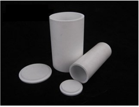
For suitable alloy systems, high-purity boron nitride crucibles can reduce wetting and provide thermal stability. Atomization hardware may use a boron nitride atomizing nozzle, a customized ZSBN nozzle for vacuum induction equipment, or a zirconia nozzle for metal-powder production, depending on temperature, alloy compatibility, erosion, geometry, and thermal-shock requirements.
Material selection should be validated with the actual melt, not only a catalog temperature rating. Chemical compatibility, open porosity, grain-boundary phases, machining tolerance, surface finish, wall thickness, preheating practice, and the expected heating rate can determine whether a component remains stable during repeated cycles.
Common VIGA and EIGA Operating Problems
| Symptom | Likely causes | Check first |
|---|---|---|
| Delivery tube or nozzle blockage | Insufficient superheat, gas backflow, cold component, unstable pouring | Preheat profile, melt temperature, nozzle pressure field, and outlet geometry |
| Excess satellites | Particle recirculation and collision between cool fines and hot coarse droplets | Gas pressure, chamber flow, collector position, and anti-recirculation measures |
| High oxygen or inclusions | Feedstock surface, refractory reaction, chamber leak, gas impurity, or handling | Mass balance of contamination sources from charge preparation to packaging |
| Broad particle-size distribution | Variable melt flow, poor jet alignment, inconsistent gas-to-metal ratio | Time-resolved melt rate, gas flow, nozzle concentricity, and electrode stability |
| EIGA melt interruption or electrode breakage | Electrode runout, surface defects, unstable induction coupling, feed mismatch | Bar geometry, rotation/feed control, coil position, and melting power |
The most reliable VIGA versus EIGA decision starts with the alloy and the acceptable contamination path, then moves through feedstock availability, melt control, powder specification, productivity, and component compatibility. VIGA is not merely the “lower-temperature” option, and EIGA is not automatically the “higher-quality” option. When the complete melting, atomization, and handling system is evaluated together, each process can produce high-quality spherical powder within a properly qualified operating window.
Frequently Asked Questions
Need application-specific crucible or atomizing-nozzle material support?
Contact Our TeamEngineering References
- Wu et al., “Effect of Electrode Induction Melting Gas Atomization on Powder Quality: Satellite Formation Mechanism and Pressure,” Materials, 2023.
- “Properties of Electrode Induction Melting Gas Atomization- and Vacuum Induction Melting Atomization-Produced Powders,” Materials, 2025.
- Qaddah et al., “Numerical Modeling of EIGA and VIGA Atomization Processes,” 2025.
- Leibniz University Hannover, EIGA/VIGA inert gas powder atomization facility and technical data.
- Spitans et al., “Numerical Modeling and Optimization of Electrode Induction Melting for Inert Gas Atomization (EIGA),” 2020.