A high dielectric constant means a material polarizes strongly in an electric field and can store more electrical energy than a low-k material. It does not automatically mean better insulation. For ceramic insulators, insulation performance depends more on dielectric strength, volume resistivity, dielectric loss, defects, moisture, temperature, frequency, and part geometry.
This distinction is important for advanced ceramic selection. Alumina, aluminum nitride, silicon nitride, boron nitride composites, and beryllium oxide can all be electrical insulators, but each material solves a different mix of voltage, heat, frequency, mechanical stress, and manufacturing requirements.
What Does High Dielectric Constant Mean?
Dielectric constant, also called relative permittivity, describes how much electric polarization a material develops compared with vacuum. It is commonly written as k, kappa, or εr. A higher value means the material can reduce the effective electric field inside a capacitor structure and store more charge for the same geometry.
εr = ε / ε0 = C / C0
In practical engineering language, higher dielectric constant usually means:
- stronger polarization under an electric field;
- higher capacitance in capacitor-like structures;
- lower signal velocity in high-frequency transmission media;
- more need to check frequency, temperature, moisture, impurities, and microstructure.
That is why the phrase "high dielectric constant" has different meanings in different applications. For capacitor design, it can be useful. For RF substrates, it may increase signal delay or impedance sensitivity. For ceramic insulator design, it is only one property in a much larger decision.
Does Higher Dielectric Constant Mean Better Insulation?
No. A higher dielectric constant does not necessarily mean better insulation. It means stronger polarization and higher energy-storage capability under an electric field. Better insulation normally requires high dielectric strength, high volume resistivity, low leakage current, low dielectric loss, and a defect-controlled ceramic microstructure.
This distinction matters because many insulating ceramics can have similar dielectric constants but very different breakdown performance. A dense alumina ceramic part, a silicon nitride substrate, and a boron nitride composite may all act as electrical insulators, but they are selected for different combinations of thermal conductivity, fracture toughness, voltage withstand, machinability, and service temperature.
For high-voltage ceramic components, ask whether the ceramic can maintain insulation at the required voltage, temperature, frequency, humidity, surface finish, and part thickness.
Dielectric Constant vs Dielectric Strength
| Property | What it measures | Unit | Insulation impact |
|---|---|---|---|
| Dielectric constant | Polarization and capacitance compared with vacuum | Dimensionless | Not a direct measure of insulation strength |
| Dielectric strength | Electric field at which breakdown occurs | kV/mm, MV/m, or V/mil | A core high-voltage withstand property |
| Volume resistivity | Resistance to current through the bulk material | Ω·cm | Limits leakage current under DC or low-frequency voltage |
| Dielectric loss | Electrical energy converted to heat | Loss tangent or factor | Lower loss is critical for RF, microwave, and thermal aging |
| Thermal conductivity | Heat removal through the ceramic | W/(m*K) | Helps reduce hot spots that accelerate leakage or breakdown |
Dielectric strength also depends on geometry. Thin, dense, defect-controlled layers can withstand higher electric fields than thick or porous parts of the same material. Edge radius, electrode shape, voids, inclusions, moisture, and local heating all influence breakdown.
When Is High Dielectric Constant Useful?
High dielectric constant is useful when the design goal is charge storage, field control, or device scaling. It is not automatically useful when the design goal is simple electrical isolation.
Capacitors and Energy Storage
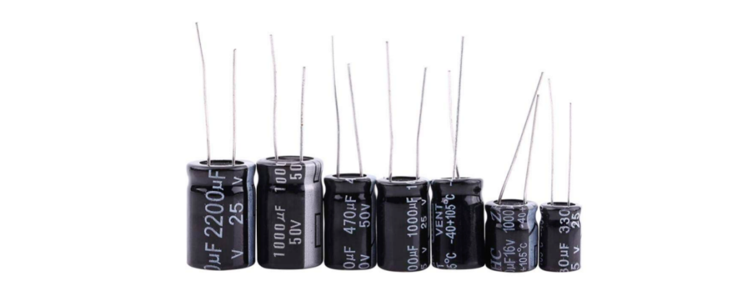
In a capacitor, capacitance increases with dielectric constant when area and thickness remain the same. This is why capacitor dielectrics often use higher-k materials. However, a capacitor dielectric still needs high breakdown strength and acceptable loss. A high-k material with high loss or low breakdown voltage may overheat or fail under real operating conditions.
High-k Semiconductor Dielectrics
In semiconductor manufacturing, high-k dielectrics are used because they can provide high capacitance without making the physical layer extremely thin. This helps reduce leakage caused by very thin dielectric layers. This is a specialized semiconductor use case; it does not mean every high-k material is a better general insulator.
Electric Field Control
Higher-k materials can influence how an electric field distributes around a part. In some assemblies, this can help reduce local field concentration. But field control still requires simulation or careful design. A material property alone cannot compensate for sharp edges, voids, poor bonding, or surface contamination.
When Is a Lower Dielectric Constant Better?
A lower and stable dielectric constant can be better for high-frequency circuits, RF windows, microwave components, and high-speed electronic substrates. In these applications, signal velocity is related to dielectric constant. Higher dielectric constant generally slows signal propagation and can make impedance control more sensitive.
For RF and high-speed applications, engineers normally care about:
- dielectric constant at the operating frequency, not only at 1 MHz;
- dielectric loss under the same frequency and temperature range;
- thermal conductivity and coefficient of thermal expansion;
- thickness tolerance, flatness, surface roughness, and long-term drift.
For this reason, aluminum nitride substrates, silicon nitride substrates, alumina substrates, and boron nitride composites are not selected by dielectric constant alone. They are selected by a balanced property set.
How to Choose Advanced Ceramic Insulators
Use the following worksheet before selecting an advanced ceramic insulator. It helps separate a dielectric-constant question from a real insulation-design question.
| Design input | What to define | Why it changes material choice |
|---|---|---|
| Voltage | DC, AC, pulse voltage, peak voltage, and safety margin | Determines dielectric strength, creepage, and clearance needs |
| Frequency | DC, 50/60 Hz, kHz, MHz, or GHz | Changes the importance of dielectric loss and stable permittivity |
| Temperature | Continuous and peak temperature | Affects resistivity, loss, thermal expansion, and oxidation |
| Heat load | Power density and cooling path | Determines whether AlN, Si3N4, BeO, or alumina is more suitable |
| Geometry | Thickness, edges, holes, metallization, and surface distance | Controls local electric field and breakdown risk |
| Environment | Humidity, vacuum, plasma, molten metal, or chemicals | Influences leakage, oxidation, corrosion, and contamination |
If the application is a high-voltage standoff, feedthrough, or spacer, start with dielectric strength and resistivity. If it is a power-module substrate, include thermal conductivity and thermal cycling. If it is RF or microwave hardware, prioritize dielectric loss and stable dielectric constant.
Advanced Ceramic Material Selector
The values below use Cersol internal product data where available. Exact values vary by grade, purity, forming process, thickness, surface finish, and test condition. Confirm the final grade with a Cersol technical data sheet before design release.
| Cersol material | Internal data to use in selection | Best-fit insulation use | Watch-outs |
|---|---|---|---|
| Alumina ceramic, A96 to A999 | Dielectric constant 9.4 to 9.9 at 1 MHz; dielectric breakdown 14 to 15 kV/mm; volume resistivity >1014 to >1015 Ω·cm; thermal conductivity 26 to 34 W/(m*K); dielectric loss down to 2.2 × 10⁻⁴ for A999. | General ceramic insulators, wear-resistant insulating parts, electronic substrates, and high-temperature insulating structures. | Brittle under impact; difficult post-sintering machining; listed thermal shock limit around 200 to 250°C. |
| Aluminum nitride substrate | Permittivity 8 to 10; common thicknesses include 0.381 mm, 0.5 mm, and 1.0 mm; positioned for LED packages, power resistor ceramic base boards, and high-power semiconductor devices. | Electrically insulating substrates that must move heat quickly. | More expensive than alumina; confirm breakdown voltage, resistivity, and thermal conductivity by grade. |
| Silicon nitride ceramic | Dielectric constant 8 to 10 at 1 MHz; dielectric loss <0.001 to 0.005; volume resistivity >1014 Ω·cm; thermal conductivity 15 to 30 W/(m*K); flexural strength 600 to 1000+ MPa. | High-reliability insulators that also need toughness, wear resistance, thermal shock resistance, and high-temperature strength. | Usually selected for reliability and mechanical performance rather than lowest cost. |
| Silicon nitride substrate | Dielectric constant 7.8; breakdown strength >25 kV/mm; volume resistivity 1014 Ω·cm; thermal conductivity >80 W/(m*K); bending strength >700 MPa, typical 800 MPa; fracture toughness >6.5 MPa*m1/2. | EV inverter substrates, power modules, high thermal cycling assemblies, and mechanically demanding insulating substrates. | Thermal conductivity is lower than typical AlN, but strength and toughness can allow thinner, more reliable designs. |
| Boron nitride composites | Electrical resistivity listed from >1012 to >1014 Ω·cm depending on grade; thermal conductivity 30 to 85 W/(m*K); max service temperature up to 900 to 1000°C in air and 1750 to 2100°C in inert gas depending on grade. | High-temperature electrical insulators, furnace parts, molten-metal contact parts, and machinable insulating components. | Dielectric constant values should be confirmed by grade; BN oxidizes in oxygen-rich environments above about 900 to 1000°C. |
| BN-AlN composite, C-BN-A3 | Composition BN + AlN; electrical resistivity >1013 Ω·cm; thermal conductivity 85 W/(m*K); bending strength 120 MPa; compressive strength 220 MPa. | High-temperature electrical insulators that need better thermal conductivity than standard BN. | Use when low dielectric loss and thermal management matter; confirm dielectric constant for the exact grade. |
| BeO ceramic | Cersol describes BeO as having thermal conductivity about 10 times alumina, lower dielectric constant and medium loss, reliable insulation, high-temperature resistance, and use in microelectronics, communication devices, LEDs, and power modules. | High-thermal-conductivity electrical insulation where BeO is allowed by safety and process controls. | Machining dust requires qualified handling; confirm regulatory and safety requirements before specifying. |
Practical Material Selection Shortcuts
- Choose alumina when you need a balanced, cost-effective ceramic insulator with proven dielectric strength and stable supply.
- Choose aluminum nitride when heat dissipation is the main constraint and the part must remain electrically insulating.
- Choose silicon nitride when thermal cycling, vibration, fracture resistance, and power-module reliability are more important than material cost.
- Choose boron nitride composites when machinability, high-temperature service, thermal shock resistance, and non-wetting behavior matter.
- Choose BeO only when its thermal performance is necessary and your supply chain can handle BeO safely.
Common Mistakes When Interpreting Dielectric Constant
Mistake 1: Treating dielectric constant as insulation strength
Dielectric constant is about polarization. Dielectric strength is about breakdown. A material can have a useful dielectric constant but still fail if it has voids, contamination, poor geometry, or insufficient thickness.
Mistake 2: Comparing values without frequency
Dielectric constant and dielectric loss can change with frequency. A value measured at 1 MHz is useful for comparison, but it may not predict behavior at GHz frequencies or under fast pulses. Always match data to the working frequency.
Mistake 3: Ignoring loss and heat
Loss turns electrical energy into heat. In high-frequency or high-power designs, heat can accelerate aging, increase leakage, and push the ceramic closer to breakdown. Low loss and good thermal conductivity often matter more than a higher dielectric constant.
Mistake 4: Forgetting surface leakage
Bulk ceramic data can look excellent, but real parts fail at surfaces, edges, metallized interfaces, or contaminated creepage paths. Cleaning, surface finish, edge radius, humidity control, and assembly design are part of insulation performance.
Recommended Data to Send for Material Selection
When requesting a ceramic insulator recommendation, send:
- operating voltage, waveform, and safety factor;
- operating frequency and whether the part sees RF, pulse, or DC stress;
- continuous and peak temperature;
- heat load or thermal conductivity target;
- drawing, thickness, holes, edges, and metallization requirements;
- service environment, such as humidity, vacuum, plasma, molten metal, or chemical exposure;
- mechanical loads, vibration, impact, and thermal cycling.
Cersol can then compare alumina, aluminum nitride, silicon nitride, boron nitride composites, zirconia, and BeO options against the real operating conditions instead of ranking materials by dielectric constant alone.
High dielectric constant meaning is simple at the physics level: stronger polarization and more capacitance. In real ceramic insulator design, a high-k material is not automatically a stronger insulator, and a lower-k material is not automatically weaker. Use dielectric constant as one screening property, then validate the full design against voltage, temperature, frequency, thermal load, geometry, and operating environment.
FAQ
Need custom ceramic insulator or substrate support?
Contact Our Team