Technical Article
How to Specify Tolerances for Precision Ceramic Parts Without Overpaying
The economical way to specify precision ceramic tolerances is to tighten only the dimensions and geometric relationships that control fit, sealing, alignment, motion, electrical spacing, or another verified function. Define those requirements from assembly datums, then allow noncritical surfaces to follow a suitable as-fired or supplier-standard capability.
Do not begin by copying a global metal-machining tolerance onto every dimension. A technical ceramic may be formed near net shape, machined before sintering, diamond-ground after sintering, lapped, polished, coated, metallized, or brazed. Each transition adds a different combination of setup time, tool wear, handling risk, inspection, and yield loss. A small numerical change can therefore move a feature into a different manufacturing route rather than add a small, proportional cost.
There is also no universal tolerance table for all ceramic parts. Capability depends on material grade, part size, shape, wall thickness, feature access, length-to-diameter ratio, forming route, sintering behavior, grinding stock, surface condition, and measurement method. Treat a published capability value as a discussion starting point, not as a promise that applies to every feature.
Contents
- Why ceramic tolerances change the process
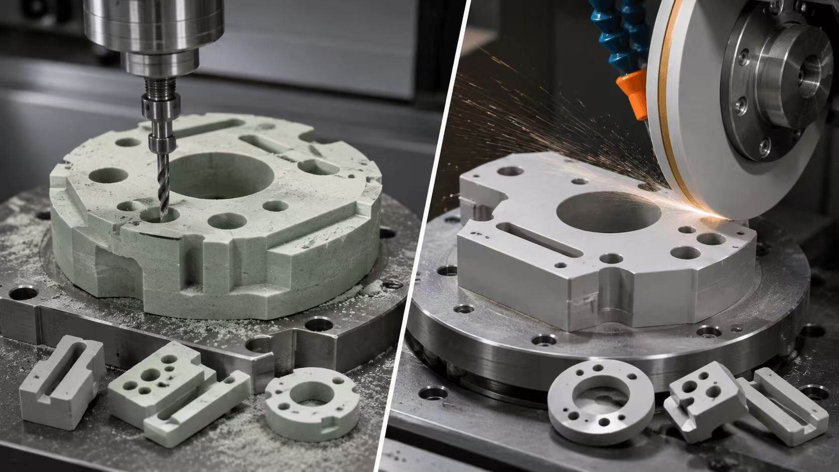
- As-fired, green-machined, and fired-ground tolerances
- Four classes for allocating precision
- Step-by-step tolerance specification method
- Feature-by-feature specification guide
- What actually drives tolerance cost
- Illustrative drawing revision
- Drawing review checklist
Why Ceramic Tolerances Change the Process, Not Just the Inspection
Dense technical ceramics are hard and wear resistant, which is exactly why post-sintering material removal normally requires diamond tooling. Unlike a ductile metal, a ceramic offers little opportunity to correct a poor setup by bending, burnishing, or forcing the part into assembly. It is also sensitive to edge damage, local tensile stress, and surface or subsurface grinding flaws.
The lowest-cost route is often to form the component close to final shape and leave suitable surfaces as-fired. Tighter relationships may be created through green machining before full densification or by grinding selected features after firing. Very demanding flatness, finish, thickness uniformity, or optical contact may add lapping and polishing.
This produces a cost ladder:
- near-net forming and as-fired acceptance;
- green machining followed by firing;
- selective hard grinding of functional features;
- multi-surface precision grinding with repeated setups;
- lapping, polishing, custom cleaning, and enhanced inspection.
The steps can overlap, and the best route varies by geometry and quantity. The important point is that tolerance cost is often discontinuous. If one requirement forces the whole part from level 1 to level 3, the cost impact can be much larger than the tolerance value alone suggests.
As-Fired, Green-Machined, and Fired-Ground Tolerances
| Process State | Best Use | Main Limitations | Cost Implication |
|---|---|---|---|
|
As-fired or unground Forming and sintering establish final geometry. |
Noncritical outside dimensions, clearances, protected surfaces, and economical production shapes | Shrinkage, distortion, draft, camber, and local geometry affect capability | Usually the lowest recurring cost when the design accepts the process |
|
Green-machined then fired An oversized unfired or partially fired blank is machined before densification. |
Complex passages, grooves, holes, and near-net features that would be expensive to hard-machine | The supplier must compensate for shrinkage; final size and form still include firing variation | Often reduces diamond grinding but requires controlled process allowance |
|
Fired-ground A dense fired blank is ground with diamond tools. |
Datums, locating diameters, seal faces, controlled thickness, flatness, parallelism, and precise hole relationships | Tool access, fixturing, grinding damage, edge risk, and stock removal matter | Higher cost; reserve it for features that close a functional requirement |
|
Lapped or polished Fine abrasive finishing follows grinding or a prepared surface. |
Very low roughness, close flatness, sealing, optical, semiconductor, or wear interfaces | Adds process time, cleaning, handling, and specialized metrology | Use only where a verified function requires it |
These are process states, not universal tolerance grades. Exact capability must be reviewed against the actual material, feature, geometry, lot size, and measurement plan.
A short, thick alumina ring and a long, thin zirconia tube do not share the same capability simply because both are described as ground. For material-specific planning, the manufacturing response can also differ between alumina ceramic and zirconia ceramic. Grade, microstructure, hardness, toughness, part size, and blank availability all influence the practical route.
Use Four Classes to Allocate Precision
Before assigning numbers, classify every dimension or geometric control by its job.
| Class | Purpose | Typical Examples | Specification Approach |
|---|---|---|---|
| A. Functional closure | Directly determines whether the assembly works | Seal-face relationship, bore-to-shaft fit, electrode gap, optical alignment, or controlled flow orifice | Calculate from the tolerance stack and verify by inspection |
| B. Locating relationship | Establishes repeatable orientation or position | Primary mounting face, bore axis to mounting pattern, or parallel guide faces | Use a coherent datum reference frame and GD&T |
| C. Process clearance | Prevents interference without closely controlling performance | Housing clearance, tool relief, or noncontact outside envelope | Give enough tolerance for assembly and invite an economical process state |
| D. Reference or informational | Helps explain the design but does not control acceptance | Derived overall size, repeated model dimension, or approximate location | Mark as reference or remove duplicate control |
Class A features deserve the tolerance budget. Class B features make Class A measurable and repeatable. Class C features should normally be as loose as the assembly permits. Class D information must not accidentally become a second, conflicting acceptance requirement.
This framework also exposes a common drawing problem: a feature may be tightly sized but poorly located. A precision bore diameter does not guarantee that its axis aligns with a mounting face. In that case, spending more on size may not improve the assembly. A position, perpendicularity, or runout control related to functional datums may communicate the need more directly.
A Step-by-Step Method for Specifying Ceramic Part Tolerances
1. Start With the Functional Tolerance Stack
Identify what must close in the final assembly. It may be:
- clearance between a ceramic sleeve and a metal shaft;
- compression of a seal between two faces;
- alignment between a bore and an optical, fluid, or electrical path;
- minimum wall thickness after all dimensional variation;
- spacing between electrodes or conductive coatings;
- installed height across a stack of ceramic and metal parts.
Work backward from the allowable assembly variation. Include variation from mating parts, coatings, adhesive or braze layers, temperature, clamp load, and measurement. Do not give the ceramic the entire tolerance budget by habit. Allocate variation according to function, process capability, and the cost of controlling each contributor.
If the calculation shows that the proposed ceramic tolerance is unnecessarily restrictive, relaxing it is an engineering decision, not a quality concession.
2. Choose Datums From How the Part Is Assembled
The datum reference frame should stabilize the ceramic in the same logical way the assembly does. A primary mounting or sealing face may remove three degrees of freedom; a locating diameter or side face may establish the next two; a hole, slot, or secondary face may clock the part.
Avoid choosing a rough, curved, fragile, or inaccessible as-fired surface as the primary datum unless the real assembly uses it. An unstable datum can force special fixtures and produce disagreement between the supplier's inspection result and the customer's result.
For parts that are ground in several setups, the datum scheme also affects how many times the component must be relocated. A coherent scheme can reduce compounded setup error and make inspection easier. An arbitrary scheme can turn a simple size requirement into a multi-axis alignment problem.
3. Decide Which Features May Remain As-Fired
Review every surface and ask:
- Does it contact or locate another component?
- Does it seal, guide, rotate, meter flow, or control an electrical gap?
- Does it need a controlled surface texture?
- Is the feature accessible to a grinding wheel or inspection probe?
- Would normal forming draft, shrinkage, camber, or edge radius affect function?
If the answer is no, consider supplier-standard as-fired acceptance. This does not mean uncontrolled. The drawing can still define an envelope, minimum wall, interface clearance, or visual zone without requiring finish grinding.
It is often economical to grind only a primary face, one locating diameter, and a small set of critical features while leaving the rest as-fired. Mark the process-state boundary clearly so the supplier does not assume that every modeled surface must be machined.
4. Separate Size From Geometry
A plus/minus size tolerance controls size. It does not fully control flatness, straightness, perpendicularity, parallelism, position, concentric behavior, or runout.
Use the requirement that matches the function:
- Size controls a thickness, diameter, width, or gap.
- Flatness controls one surface independently of a datum.
- Parallelism controls orientation relative to a datum.
- Perpendicularity controls a face or axis at 90 degrees to a datum.
- Position controls the location of holes, slots, or axes from basic dimensions and datums.
- Profile can control a complex surface or a set of related surfaces.
- Runout controls rotating behavior relative to a datum axis.
ASME Y14.5 and ISO 1101 provide established languages for dimensioning and geometric tolerancing. Declare the standard and edition that govern the drawing, and apply the system consistently. GD&T itself does not make a ceramic expensive. Cost rises when the controls are tighter than function requires, depend on impractical datums, or require difficult fixturing and measurement.
5. Keep Surface Texture Separate From Flatness
Surface texture describes small-scale surface features. Flatness describes the overall form of a surface. A face can be smooth but bowed, or flat at the macroscopic level while retaining measurable grinding texture.
Specify roughness only on the surfaces where friction, sealing, electrical contact, particle generation, coating adhesion, optical behavior, or wear requires it. Name the parameter and limit, the affected surface, the measurement direction when relevant, and the governing standard. ISO 21920-1 defines how profile surface texture is indicated in technical product documentation.
Do not apply an optical or lapped finish to hidden clearance surfaces merely for consistency. Also avoid expecting a roughness value to guarantee leak tightness; waviness, flatness, porosity, scratches, edge condition, and the mating seal can all matter.
6. Define Edges, Chips, Radii, and Sharp Zones
Ceramic edges need explicit treatment because "break all sharp edges" and "no chips" are open to interpretation. Define:
- intentional chamfers or radii;
- edges that must remain functionally sharp;
- maximum permissible chip size;
- zones where chips are prohibited, such as seal lands or thin electrical barriers;
- visual inspection magnification and lighting when they affect acceptance;
- whether edge dimensions apply before or after coating, metallization, or brazing.
Very small edge breaks and sharp internal corners can increase machining difficulty and local stress. A practical radius or chamfer may improve both yield and handling durability. The correct value depends on the part, so ask for a costed manufacturability alternative instead of accepting an undocumented shop default.
7. Account for Long Bores, Thin Walls, and Hard-to-Reach Features
The same numerical tolerance can have very different difficulty on different features. Review:
- bore length relative to diameter;
- wall thickness and unsupported spans;
- deep grooves, blind features, and intersecting holes;
- small corner radii and interrupted surfaces;
- large flat areas;
- features that require grinding close to a fragile edge.
A short accessible outside diameter may be straightforward to grind and measure. A long small bore may require specialized tooling, limited stock removal, and different metrology. Tight wall-thickness control may require both inside and outside surfaces to be related in one datum scheme. Large thin plates can be affected by support conditions during both machining and inspection.
Use a section view and identify the functional portion of a feature. If only the first few millimeters of a bore provide guidance, controlling the full length to the same condition may add cost without improving performance.
8. Specify the Final Process State
State whether dimensions apply:
- as-fired;
- after grinding, lapping, or polishing;
- after glaze, coating, or metallization;
- after brazing or bonding;
- after final cleaning;
- at an agreed reference temperature and support condition.
This matters because secondary processes can add thickness, round an edge, distort a thin part, or change the datum surface. A drawing that controls the bare ceramic while the assembly needs the metallized or brazed condition leaves an acceptance gap.
For high-temperature assemblies, calculate whether thermal expansion changes the functional fit. Dimensional metrology is commonly referenced to 20°C, and NIST guidance explains why temperature and coefficient-of-thermal-expansion uncertainty matter in precise length measurement. The service fit and the inspection condition are different questions; define both where necessary.
9. Make the Inspection Requirement Quotable
A tolerance is incomplete as a purchasing requirement when the measurement basis is ambiguous. For critical features, define:
- the characteristic and datum simulation;
- measurement equipment or an acceptable method where method sensitivity matters;
- support, clamping, and orientation for flexible or thin parts;
- measurement temperature and stabilization;
- sampling frequency or 100% inspection requirement;
- first-article, lot, or final inspection records;
- rounding and conformity decision rules near a specification limit.
ISO 14253-1 addresses conformity and nonconformity decisions while considering measurement uncertainty. This becomes important when the tolerance approaches the uncertainty of the selected measurement system. Demanding a very tight number without budgeting for a capable method can create disputes or expensive inspection that was not included in the original quote.
Do not require full recorded reports for every noncritical dimension unless the documentation serves a real quality need. A certificate of conformance, sampled dimensional report, or complete first-article report may each be appropriate in different stages.
10. Ask for a Costed Tolerance Review
Send the 3D model, controlled 2D drawing, material or property requirements, assembly interfaces, quantity tiers, and service conditions. Then ask the supplier to return:
- which features will be as-fired, green-machined, ground, lapped, or polished;
- any capability exceptions by feature;
- proposed datum or inspection changes;
- the tolerance, finish, or edge requirements driving cost;
- a compliant baseline price and clearly identified alternatives;
- tooling, fixtures, non-recurring engineering, and inspection charges;
- assumptions about blanks, stock allowance, sampling, and yield.
A useful DFM alternative should state the exact requirement to change, the resulting process simplification, the cost or lead-time effect, and the functional risk to verify. "Relax all tolerances" is not engineering guidance.
Feature-by-Feature Specification Guide
| Feature | Specify When Functional | Common Over-Specification | Supplier Question |
|---|---|---|---|
| Outside or inside diameter | Fit, seal, rotation, flow, or wall thickness | Tight size on the full length when only a short land functions | Which length must be ground and gauged? |
| Flat face | Seal, mounting stability, heat transfer, or wafer support | Tight flatness and low roughness on every face | Can only the functional face be ground or lapped? |
| Two opposing faces | Installed height, parallel guidance, or controlled thickness | Tight thickness plus flatness and parallelism without a stack analysis | Which characteristic actually controls assembly? |
| Hole pattern | Fastener clearance, alignment, or electrical spacing | Bilateral coordinate tolerances without functional datums | Can basic dimensions and position express the requirement? |
| Long bore | Guidance, metering, or a through-path | One tight diameter and straightness condition across unnecessary depth | What functional length and gaging method are required? |
| Thin wall | Electrical barrier, flow path, thermal response, or mass | Tight inside and outside sizes without defining minimum wall | Can minimum wall or profile control the risk more directly? |
| Edge | Seal boundary, controlled contact, electrical creepage, or handling | "No chips" or a near-zero edge break everywhere | Which zones are critical, and what chip size is acceptable elsewhere? |
| Surface texture | Seal behavior, friction, wear, coating, optics, or cleanliness | One low Ra note applied to all surfaces | Which parameter, direction, area, and process state matter? |
What Actually Drives Tolerance Cost
Moving to a Different Process State
The largest cost change often occurs when a feature can no longer remain as-fired. Selective grinding requires a suitable oversized blank, machining allowance, diamond tooling, setup, handling, cleaning, and inspection. Lapping or polishing adds another controlled operation.
Number of Ground Surfaces and Setups
One ground datum face is different from six mutually related ground faces. Every relocation can require a fixture, alignment, intermediate inspection, and protection of completed surfaces. Requirements that relate features across inaccessible orientations are especially likely to add setups.
Material Removal and Tool Access
Deep bores, blind corners, narrow slots, small radii, interrupted cuts, and large stock allowances can slow removal. Grinding near thin edges raises chipping risk. A design that gives the wheel a stable, accessible path is usually easier to produce than one with the same tolerance in a confined feature.
Part Geometry and Handling Risk
Long, thin, asymmetric, or large-area parts may deflect under support, distort during firing, or break during repeated handling. Cost can reflect lower yield and specialized fixtures even when the nominal tolerance does not look extreme.
Inspection and Acceptance Evidence
Tight position, flatness, profile, or texture may require a CMM, optical system, roundness instrument, profilometer, interferometric method, or custom gage. Recorded reports, 100% inspection, measurement-system studies, and customer-specific forms add time independently of machining.
Quantity and Process Capability
A prototype machined from a standard blank may avoid tooling but carry high unit cost. Repeat demand may justify near-net forming, dedicated fixtures, or process development. Ask for prototype, pilot, and production quantities separately so the quotation does not optimize the wrong stage.
An Illustrative Drawing Revision
Consider a ceramic insulating ring located in a metal housing. The first drawing applies a global ±0.01 mm tolerance to every linear dimension, requires very low roughness on all surfaces, adds tight flatness to both faces, and does not identify datums. The actual assembly uses one face for seating, one outside diameter for location, and one bore only as conductor clearance.
An improved drawing could:
- establish the seating face as primary datum A;
- use the locating outside diameter as datum B;
- control installed height and the functional relationship between A and B;
- define the bore by the clearance needed at worst-case assembly;
- apply flatness or roughness only to the seating face if the interface needs it;
- leave noncontact outside surfaces and the nonfunctional face to an agreed as-fired envelope;
- define edge breaks and prohibited chip zones around the seating land;
- identify the final inspection state after any coating or metallization.
Important: The ±0.01 mm value is illustrative, not a recommended ceramic tolerance. The savings come from changing the control strategy: precision is concentrated on the seating and locating functions instead of being repeated across the whole part.
Drawing Review Checklist Before RFQ
- Is each tight tolerance connected to a documented fit, seal, alignment, motion, flow, electrical, optical, or minimum-wall requirement?
- Has the assembly tolerance stack been calculated?
- Do the datums match how the part is mounted and inspected?
- Are as-fired and machined surfaces distinguished?
- Are size, form, orientation, location, runout, and surface texture controlled separately?
- Are long bores, thin walls, fragile edges, and tool access reviewed?
- Are coating, metallization, glaze, braze, and adhesive layers included in the dimensional state?
- Are edge and chip requirements measurable and zoned?
- Are inspection method, support, temperature, sampling, and reports defined where needed?
- Does the RFQ invite a costed alternative without allowing an undocumented deviation?
The custom ceramic manufacturing review should happen before tooling or a production blank is committed. That is the point when a datum change, selective grinding plan, practical radius, or revised inspection method can remove cost without compromising the assembly.
Good tolerance design is not the loosest drawing and not the tightest drawing. It is a drawing in which every controlled relationship has a functional reason, every critical feature has a stable datum and inspection basis, and every noncritical surface is free to use an economical ceramic process. That gives the supplier room to manufacture efficiently while giving the buyer a clear, defensible acceptance standard.
Frequently Asked Questions
Have a precision ceramic drawing ready for a tolerance and manufacturability review?
Request a Technical ReviewEngineering References
- ASME Y14.5-2018 (R2024), Dimensioning and Tolerancing
- ISO 1101:2017, Geometrical Product Specifications - Geometrical Tolerancing
- ISO 21920-1:2021, Surface Texture - Indication of Surface Texture
- ISO 14253-1:2017, Decision Rules for Verifying Conformity or Nonconformity
- NIST, Ceramic Machining
- NASA-HDBK-6007B, General Design and Construction Considerations for Spaceflight Hardware
- NIST, Uncertainties in Dimensional Measurements Made at Nonstandard Temperatures