10-February-2026
In the pursuit of scientific discovery and industrial precision, humanity has found it necessary to create environments that are hostile to life but essential for physics. The vacuum chamber is the stage for semiconductor manufacturing, scanning electron microscopy, and surface science. The dilution refrigerator creates temperatures colder than the cosmic microwave background to stabilize quantum bits. The pressure vessel protects sensitive electronics at the bottom of the Mariana Trench.
However, a perfectly sealed chamber is useless if it is isolated. To perform work, we must inject energy, extract data, and control internal mechanisms. This necessitates a penetration through the chamber wall—a component technically known as a "feedthrough."
While a simple metal rod can carry electrical current (a power feedthrough), it fails catastrophically when carrying complex, high-speed signals. Radio Frequency (RF) and microwave signals, essential for everything from plasma excitation to reading qubit states, behave like waves. When they encounter a mismatch in the transmission path—such as a simple wire pin passing through a steel wall—they reflect, distort, and degrade.
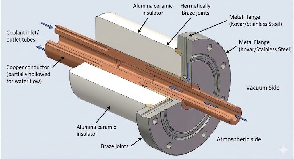
The Coaxial Feedthrough is the engineering solution to this paradox. It is a precision-engineered component that extends the geometry of a coaxial cable through a hermetic barrier. It ensures that the electromagnetic wave sees a continuous, unchanging environment as it transitions from the air side to the vacuum side, all while preventing a single molecule of gas from leaking through.

The geometry is critical for maintaining constant impedance (Z0). The diagram illustrates the "Coaxial" nature—two axes sharing a center—and the "Hermetic Seal" formed by the braze joints between the metal and ceramic components.
The importance of these components cannot be overstated. In the ITER nuclear fusion reactor, a failure in a feedthrough's seal could vent radioactive tritium or quench the superconducting magnets, halting a multi-billion dollar experiment. In a quantum computer, a feedthrough that fails to properly shield the signal introduces thermal noise, causing "decoherence" and collapsing the quantum state of the processor. In semiconductor manufacturing, a micro-leak in a feedthrough can introduce oxygen into a process chamber, ruining millions of dollars worth of silicon wafers.
To understand why coaxial feedthroughs are designed with such specific geometries and materials, one must delve into the physics of electromagnetic wave propagation and transmission line theory.
In Direct Current (DC) circuits, we concern ourselves primarily with resistance. In Alternating Current (AC) and RF circuits, we must manage Impedance (Z). When a signal travels down a conductor at high frequencies, it does not travel instantaneously; it travels as a wave of voltage and current. If this wave encounters a change in the impedance of the line, a portion of the wave energy is reflected back toward the source, much like light reflecting off a window.
This reflection causes two primary issues:
The characteristic impedance of a coaxial line is determined not by the length of the cable, but by its cross-sectional geometry and the materials used. The governing formula is:
Where:

As the dielectric constant (εr) increases (e.g., changing from air to ceramic), the ratio D/d must increase to maintain the same impedance (Z0). This explains why the central pin often looks thinner inside the ceramic part of a feedthrough compared to the air-side cable.
Almost all commercial vacuum feedthroughs are designed to have a characteristic impedance of 50 Ohms (50Ω). This value is a historical compromise derived from the physics of coaxial waveguides.
The Compromise: The arithmetic mean of 30 and 77 is 53.5. The geometric mean is closer to 48. 50 Ohms was chosen as a standard that offers a good balance: it can handle high power (essential for plasma generation and transmitters) while maintaining acceptable signal loss (essential for data transmission).
In a vacuum feedthrough, maintaining this 50Ω geometry is challenging. The dielectric material changes from the air-side cable (typically PTFE/Teflon, εr ≈ 2.1) to the feedthrough insulator (Alumina ceramic, εr ≈ 9.8) and back to the vacuum-side cable. Because Alumina has a much higher dielectric constant than Teflon, the capacitance per unit length increases drastically. To compensate and maintain 50Ω, the geometry must change inside the hermetic seal: the inner pin diameter (d) must decrease, or the outer shield diameter (D) must increase.
The handling of the outer conductor (shield) is a critical design choice in vacuum electronics.
Grounded Shield Feedthroughs: The outer conductor is electrically and mechanically bonded to the mounting flange. Since the vacuum chamber is almost always grounded for safety, the signal ground shares the system ground. This is simple, robust, and ideal for high-frequency RF where a common ground plane is desirable.
Floating Shield Feedthroughs: In sensitive instrumentation (e.g., measuring pico-amps in a Faraday cup), the vacuum chamber itself might carry electrical noise ("ground loops") from pumps and heaters. To prevent this noise from corrupting the signal, engineers use Floating Shield feedthroughs. In this design, the outer coaxial shield is electrically isolated from the metal flange by a second concentric layer of ceramic. This allows the signal ground to be kept separate from the "noisy" earth ground of the vacuum vessel.
Coaxial cables propagate energy in the Transverse Electromagnetic (TEM) mode, where both the electric and magnetic fields are perpendicular to the direction of travel. However, at very high frequencies, the dimensions of the coaxial structure become comparable to the wavelength of the signal. When this happens, higher-order "waveguide modes" (TE or TM modes) can begin to propagate. These modes travel at different speeds and interfere with the signal, causing massive distortion.
The Cutoff Frequency (fc) is the upper limit of usable frequency for a coaxial feedthrough. It is inversely proportional to the diameter of the outer conductor.
Implication: To transmit higher frequencies (e.g., 65 GHz for 5G/6G research), the feedthrough must be physically smaller. This is why 2.92mm (K-connector) and 1.85mm (V-connector) feedthroughs are used for high-frequency applications, whereas larger BNC or N-type connectors are limited to lower frequencies (typically <11 GHz).
The critical differentiator between a standard electrical plug and a high-performance vacuum feedthrough is the material science of the insulator. It must serve three conflicting roles simultaneously:
Ceramic materials are the undisputed champions of this domain. While glass was used in early vacuum tubes, modern high-performance feedthroughs rely almost exclusively on engineered ceramics.
Aluminum Oxide, or Alumina, is the most common ceramic used in feedthroughs. It offers a unique combination of properties that make it ideal for the vacuum interface.
However, not all Alumina is created equal. The purity of the ceramic dictates its performance and manufacturing method.
This grade contains sintering aids like silica (SiO2), calcia (CaO), and magnesia (MgO). These additives melt during firing to form a "glassy phase" at the grain boundaries of the alumina crystals.
Pros: The glassy phase makes the ceramic easier to metallize (see Section 4.1). It is cheaper to manufacture.
Cons: The impurities increase the Dielectric Loss Tangent (tan δ), meaning the material absorbs more energy from RF signals, converting it into heat. This makes it less suitable for high-power or extremely high-frequency applications. The glassy phase is also more susceptible to chemical attack by certain plasma process gases.
This is nearly pure crystalline aluminum oxide.
Pros: It has very low dielectric loss (<0.0001 at 1 MHz), making it superior for high-frequency RF (Microwave/Millimeter-wave) and quantum computing applications. It is chemically inert and highly resistant to fluorine/chlorine plasmas used in semiconductor etching.
Cons: It is harder, more brittle, and significantly more difficult to bond to metal because it lacks the glassy grain boundaries that traditional metallization processes rely on.
While Alumina is the standard, specific extreme environments require exotic alternatives.
Ceramics are notoriously brittle. In applications where the feedthrough might experience mechanical shock (e.g., aerospace launch vibration or deep-sea deployment), Zirconia Toughened Alumina is used. ZTA is a composite material where zirconium oxide particles are dispersed within the alumina matrix.
Mechanism: When a crack attempts to propagate through the material, it triggers a phase transformation in the zirconia particles (from tetragonal to monoclinic). This expansion compresses the surrounding material, effectively "pinching" the crack shut. This results in significantly higher fracture toughness compared to pure alumina.
For high-power RF feedthroughs, heat dissipation is the limiting factor. If the central pin gets too hot from resistive losses (skin effect), it can melt the braze joint or crack the ceramic.
Solution: Aluminum Nitride is an electrical insulator but conducts heat almost as well as metallic aluminum (170-200 W/mK, compared to Alumina's 20-30 W/mK). This allows the ceramic insulator itself to act as a heatsink, pulling heat away from the central conductor and dumping it into the water-cooled flange.
Standard ceramics must be fired in molds (expensive tooling) and ground with diamonds. Macor is a glass-ceramic containing mica flakes that arrest micro-cracks, allowing it to be machined with standard metalworking tools (lathes, mills).
Use Case: Ideal for rapid prototyping of custom feedthrough geometries in research labs. However, it is mechanically weaker than alumina and has lower thermal conductivity.
| Property | 96% Alumina | 99.8% Alumina | Aluminum Nitride (AlN) | Macor (Glass-Ceramic) |
|---|---|---|---|---|
| Dielectric Constant (εr) | ~9.4 | ~9.8 | ~8.9 | ~5.7 |
| Loss Tangent (at 1 MHz) | 0.0003 | 0.0001 | 0.0003 | 0.002 |
| Thermal Conductivity (W/mK) | 24 | 30 | 170+ | 1.5 |
| CTE (10-6/°C) | 8.2 | 8.2 | 4.5 | 9.3 |
| Machinability | Diamond Grind Only | Diamond Grind Only | Diamond Grind Only | Standard Tools |
The fundamental challenge in manufacturing a vacuum feedthrough is joining a ceramic tube to a metal pin and flange such that the bond is "hermetic"—meaning leak-tight to helium gas at a rate typically better than 1 × 10⁻⁹ mbar·L/s. You cannot use glue (it outgasses and degrades) or O-rings (they are permeable). The solution is High-Temperature Brazing.
Metals generally expand significantly when heated; ceramics expand very little. If a copper pin were brazed directly into an alumina ring and heated to 800°C for the brazing process, the copper would contract much more than the ceramic upon cooling, shrinking away from the bond or shattering the ceramic ring due to tensile stress.
To solve this, feedthroughs utilize specialized alloys like Kovar (ASTM F-15, an iron-nickel-cobalt alloy).
Kovar's Magic: The Coefficient of Thermal Expansion (CTE) of Kovar (~5.9 × 10⁻⁶/°C) is engineered to closely match that of Alumina (~6-8 × 10⁻⁶/°C) over the critical temperature range.
The Sandwich Design: The feedthrough is typically constructed with a Kovar sleeve or cap brazed to the ceramic. The Kovar acts as a transition material. This Kovar sleeve is then welded to the stainless steel flange. Since Kovar and Stainless Steel are both metals, they can be welded together (though with care due to magnetic properties), while the Kovar-Ceramic interface handles the brittle transition.
Ceramics are naturally inert; molten braze alloys will not "wet" or stick to them. To form a seal, the ceramic surface must be chemically modified.
This is the traditional method for bonding to 94-96% Alumina.
For high-purity (99%+) alumina or nitrides (AlN), which lack the glassy silicate phase required for the Moly-Mn process, Active Metal Brazing is used.
 Chemistry and Mechanism")
This image demonstrates that the seal is not merely mechanical interlocking but a chemical fusion of materials, essential for preventing gas permeation.
Beyond the mechanical seal, the feedthrough must perform as a high-fidelity transmission line.
In a perfect world, the feedthrough would look electrically identical to the cable. In reality, the transition from the cable connector to the ceramic-filled feedthrough creates an impedance discontinuity.
As frequencies increase, the current flow is restricted to a thinner and thinner layer on the surface of the conductor—the Skin Effect.
In quantum computing and particle physics, feedthroughs are often densely packed. A "Multi-Pin" feedthrough might carry 50 signal lines through a single flange.
The coaxial feedthrough enables technology in the most inhospitable places in the universe (and on Earth).
In magnetic confinement fusion (Tokamaks like ITER), the plasma must be heated to millions of degrees using high-power RF waves (Ion Cyclotron Resonance Heating - ICRH).
Superconducting quantum computers operate in dilution refrigerators at milli-Kelvin temperatures (<0.020 K).
Remotely Operated Vehicles (ROVs) and sensors on the ocean floor require video and sonar data transmission.
In the fabrication of microchips, plasma etching is used to carve features into silicon.
For the engineer or technician tasked with selecting and installing a coaxial feedthrough, practical details are as important as the physics.
The feedthrough must be mounted to the chamber. The choice of flange dictates the ultimate vacuum level.
The "Touch of Death": Never touch the ceramic face of a UHV feedthrough with bare hands. Skin oils (fingerprints) act as a contamination source, outgassing in the vacuum. Furthermore, the oil can carbonize during bake-out, creating a conductive path across the ceramic face, shorting out the signal.
Cleaning: If contaminated, feedthroughs should be cleaned with high-purity solvents (acetone, then isopropanol) and dried with nitrogen. Ultrasonic cleaning must be done with caution, as the vibration can sometimes crack the delicate ceramic-to-metal braze joints.
If a system fails to reach base pressure, the feedthrough is a prime suspect.
The demands on coaxial feedthroughs are evolving rapidly with the advancement of technology.
The coaxial feedthrough is a marvel of interdisciplinary engineering. It sits at the intersection of electromagnetics, thermodynamics, materials science, and vacuum physics. It is a passive component, often overlooked in the grand schematic of a fusion reactor or a quantum computer. Yet, without it, the active exploration of our universe—from the subatomic scale of quarks to the cosmic simulation of fusion energy—would be impossible. By mastering the art of bonding disparate materials like ceramic and metal, engineers have built a window through which we can safely interact with the most extreme environments nature and science can conjure.