25-February-2026
In the depths of modern high-tech industry and frontier scientific research, engineers and physicists often face a highly challenging physical paradox. Whether in ultra-high vacuum systems manufacturing nanoscale semiconductor chips, aerospace test chambers simulating deep space environments, or advanced powder metallurgy equipment smelting special single-crystal alloys, core physical and chemical reactions often occur inside a completely sealed "black box." These critical process chambers may be in a vacuum state close to that of deep space, or under extremely high positive pressure, accompanied by extreme high temperatures of thousands of degrees Celsius, highly corrosive chemical gases, or high-energy plasma.
This poses a seemingly simple yet extremely difficult problem for engineering designers: How can we accurately measure extreme temperatures inside a completely sealed, pressurized, or vacuum chamber without compromising its physical and hermetic seal?
Using a traditional contact thermometer is clearly inadequate for the extreme temperatures and massive pressure differences inside the chamber. Attempting to use an infrared non-contact thermometer through a glass observation window leads to severe measurement errors due to the complex radiation environment, dynamic changes in the emissivity of wafers or metal surfaces, and the limitations of specific materials regarding infrared spectrum penetration. The core contradiction is that any physical sensor connection that needs to penetrate the chamber wall from the outside can become a fatal leak path. A microscopic leak can cause a sudden collapse of the vacuum, pressure leakage, or the intrusion of external impurity gases, leading to catastrophic system failure, the scrapping of high-value products, or even equipment fires at high temperatures.
To completely break through this physical and data acquisition barrier, the engineering community has developed an indispensable key component over decades of iteration: Thermocouple Feedthrough technology. It not only addresses the core demand for accurate temperature detection but also serves as the ultimate guardian for maintaining the integrity and safety of extreme environment systems.
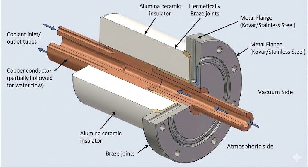
To deeply understand thermocouple feedthroughs, we first need to strip away complex engineering jargon and explain the concept in the simplest terms. You can visually describe it as a highly specialized bridge or an airtight tunnel cleverly and solidly embedded into a physical barrier, such as a heavy stainless steel vacuum bulkhead. It allows extremely weak temperature sensing electrical signals to pass safely and non-destructively from an extreme internal environment to external control and display instruments.
It must be emphasized that a thermocouple feedthrough is absolutely not just an ordinary wire passing through a wall, but a high-precision instrument that integrates materials science, thermodynamics, fluid mechanics, and precision manufacturing processes.
The working foundation of a thermocouple feedthrough relies deeply on the physical mechanism of the thermocouple itself, known as the Seebeck Effect. When two different metal conductors form a closed circuit and the two junctions are at different temperatures, an electromotive force is generated in the circuit. Modern industrial thermocouples use this principle to weld two metal alloys of different compositions together at the sensing end. As the temperature changes, the voltage difference between these two metals also changes highly predictably.
However, this voltage signal generated based on the thermoelectric effect is usually extremely weak and very susceptible to external electromagnetic interference and resistance changes. These weak signals need to be accurately transmitted to external temperature transmitters, programmable logic controllers, or simple electronic display units to be converted into meaningful temperature readings. The core mission of a thermocouple feedthrough is to provide a perfect physical channel during this signal transmission journey across extreme physical boundaries. It ensures the continuity and purity of the micro-electrical signal while physically acting like an indestructible wall, blocking any microscopic flow of gas or liquid. In this structure, specific metal conductors are responsible for conducting microvolt voltages, while the surrounding insulating medium blocks the vacuum or high-pressure environment from leaking outwards at a microscopic atomic scale, forming a seamless energy and information transmission system.

After understanding the basic functions of a thermocouple feedthrough, many engineers new to the field often ask a very intuitive question: Since we only need to conduct the voltage signal out of the chamber, why don't we just drill a hole in the stainless steel wall, bring the signal out with the most common, highly conductive, and extremely cheap ordinary copper wire, and then seal the hole with epoxy resin?
This is a very common engineering misconception. Forcibly using ordinary copper wires or general power feedthroughs to transmit thermocouple signals often leads to complete failure of the temperature reading system or even disastrously incorrect data. This misconception stems from the stereotype that a wire is just a wire, ignoring the core scientific principle that thermocouple feedthroughs rely on: material matching.
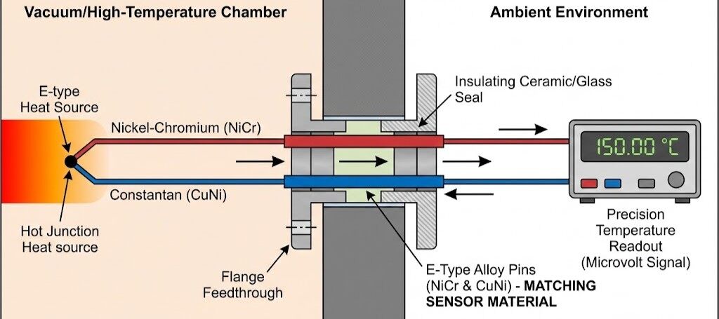
Forcibly using ordinary copper wires to transmit thermocouple signals leads to complete failure. This stems from the requirement of material matching. If copper wire is used to penetrate the bulkhead, the unified circuit is cut. New thermocouples (parasitic junctions) are formed at the junction of the thermocouple alloy and the copper wire. Because of the massive temperature gradient across the chamber wall, these junctions produce unpredictable false voltages that superimpose on the real signal. In industries like semiconductor deposition requiring accuracy of ±0.1°C, even a few millivolts of interference cause disastrous losses.
High-quality feedthroughs use metal alloy pins exactly the same as the thermocouple sensors inside. For example, an E-type thermocouple must use a feedthrough with nickel-chromium and constantan alloy pins. This eliminates the conditions for generating extra thermoelectromotive force at the interface.
| Feedthrough Type | Core Conductor Material | Design Focus | Typical Applications |
|---|---|---|---|
| Thermocouple Feedthrough | Matched thermocouple alloys or compensating materials. | Eliminating parasitic EMF and maintaining signal purity. | Vacuum furnaces, semiconductor CVD/PVD, aerospace engines. |
| Power Feedthrough | High-conductivity Copper, Beryllium Copper, or Stainless Steel. | Reducing Joule heating and preventing high-voltage breakdown. | Heaters, plasma exciters, ion sources. |
| RF / Coaxial Feedthrough | Synergistic center and shielding conductors. | Maintaining characteristic impedance and blocking EMI. | RF sputtering, high-frequency communication. |
For noble metal thermocouples (e.g., Platinum-Rhodium), using pure alloy pins is expensive. Engineers use compensating cables—alternative materials like copper and copper-nickel alloys. Within a range of 0°C to 200°C, their thermoelectric characteristic curves overlap with those of noble metals, allowing for cost-effective signal transmission without sacrificing precision.
After solving the problem of pure transmission of electrical signals, the thermocouple feedthrough must face another even more severe physical task: establishing an absolute hermetic seal around the transmission pins while ensuring absolute electrical insulation between the pins and the metal bulkhead of the chamber. If a weak thermocouple signal comes into contact with the stainless steel bulkhead, the signal will instantly disappear or cause severe ground loop problems, leading to the collapse of the entire control system.
In high-tech vacuum and pressurized engineering, ordinary polymers like plastic or rubber are completely unusable. At high temperatures, plastics soften or melt; in ultra-high vacuum environments, polymer materials experience severe outgassing and permeation, releasing volatile organic molecules and trapped water vapor that severely pollute the extremely pure vacuum environment.
This leads to the real unsung hero in thermocouple feedthrough technology: advanced ceramic materials, particularly high-purity alumina
A. Excellent electrical insulation: Alumina has an extremely low dielectric constant and high dielectric strength, up to 20 KV/mm. This completely eliminates electrical short circuits between the weak thermocouple signal and the external metal chamber wall.
B. Absolute hermeticity: The special alumina ceramics used for vacuum feedthroughs have extremely high density, and their sintered lattice structure has almost no pores that can accommodate gas molecule penetration. It is completely non-porous, making it an ideal base material for ultra-high vacuum sealing
C. Excellent thermomechanical stability: High-purity alumina has excellent thermal shock resistance, high thermal conductivity, and a low coefficient of linear thermal expansion. This allows it to cycle rapidly between high and cryogenic temperatures without cracking, with a maximum service temperature reaching up to 1800°C.
D. Strong resistance to chemical attack and wear: In environments filled with highly corrosive reaction gases, alumina shows unparalleled corrosion resistance. It can resist the erosion of strong acids, strong bases, and high-temperature plasma.
Although alumina ceramics are excellent, thermocouple alloy pins need to pass through them, and the ceramic itself needs to be hermetically fixed to a standard stainless steel vacuum flange. How to irreversibly combine these three materials with completely different physical properties and ensure atomic-level sealing is the core difficulty of the entire feedthrough technology.
Engineers must use highly complex ceramic-to-metal seal technology. The typical manufacturing process includes several steps: First, the ceramic surface is metallized using a thin coating of molybdenum and manganese powder. It is then baked in a high-temperature hydrogen furnace to form a strong mechanical and chemical bond. A nickel plating layer is added to increase wettability. Finally, in a vacuum brazing furnace, high-purity silver-copper hard brazing filler metal is used. Through capillary action, the liquid filler metal flows into the gaps, tightly combining the thermocouple pins, ceramic insulator, and metal flange into an absolutely hermetic, indivisible whole.
The physical integrity of thermocouple feedthroughs manufactured through this complex process can withstand the most rigorous scientific tests. In the industry, helium mass spectrometer leak detectors are usually used for testing. The helium leak rate of high-quality thermocouple feedthroughs is generally controlled at an extremely high level, such as ≤ 1 x 10⁻¹⁰ mbar·L/s. This means it would take hundreds of thousands of years for one milliliter of gas to leak through this seal into the vacuum system.
Like any cutting-edge engineering technology, ceramic-metal seal-based thermocouple feedthrough technology provides ultimate physical performance and data accuracy while also having some limitations that engineers must weigh in the initial system design phase. The following table details its core features, significant advantages, and disadvantages:
| Feature | Significant Advantages | Main Disadvantages |
|---|---|---|
| Signal Integrity | Absolute signal purity and zero distortion: By strictly physically matching the specific alloy material of the thermocouple sensor, parasitic electromotive force interference is fundamentally eliminated, ensuring the extremely weak thermoelectric voltage remains flawless when passing through physical barriers. | Strict alloy matching limits and inventory complexity: Poor versatility. The type of feedthrough pins purchased must exactly match the type of thermocouple used inside the vacuum system. This requires extremely high engineering planning accuracy and increases spare parts inventory complexity. |
| Durability | Impeccable vacuum sealing and extreme environment resistance: Using high-purity alumina ceramics and vacuum brazing technology, it can not only withstand ultra-high vacuum and extreme pressure but also resist corrosive chemical gases, strong radiation, and high-frequency electromagnetic interference for a long time. | Brittleness requires careful handling: Although alumina ceramics are extremely hard, their tensile strength is relatively weak compared to metals. Improper force during installation or severe mechanical impact can easily cause irreversible micro-cracks in the ceramic insulator, leading to total loss of hermeticity. |
| System Cost | Maintenance-free and highly scalable multi-channel capability: As a completely static passive component, it requires almost no post-maintenance once installed. It can also be customized into high-density multi-pin forms, simultaneously transmitting dozens of pairs of thermocouple signals through a very small flange interface. | High initial manufacturing and procurement costs: It requires complex ceramic surface metallization and precise vacuum high-temperature brazing processes. Especially when the application requires noble metal thermocouple pins, its overall manufacturing cost far exceeds ordinary copper power feedthroughs. |
By perfectly combining tiny thermocouple pins with powerful advanced ceramic sealing technology, thermocouple feedthroughs make the temperature data inside the once unreachable sealed black box clear and transparent. Here are a few of its most representative frontier applications:
Semiconductor Manufacturing: Precise wafer temperature control during CVD to ensure film growth uniformity.In the modern semiconductor industry, chemical vapor deposition and physical vapor deposition are the most critical steps in manufacturing advanced integrated circuits. In these extremely clean processes, specific precursor gases are introduced into a deep vacuum reaction chamber to form nanometer-thick material layers on the wafer surface.
The temperature of the wafer substrate is the lifeblood that determines the success or failure of the process. Extremely small temperature fluctuations can directly change the growth rate of the film, leading to catastrophic wafer scrapping. Due to the high-energy electromagnetic fields and strong corrosive reaction gases inside the environment, traditional thermometers cannot provide accurate data. High-precision miniature thermocouples are deeply embedded inside the wafer carrier substrate, and their weak temperature measurement electrical signals are transmitted out of the extremely dangerous vacuum bulkhead without electromagnetic distortion through hermetically installed custom thermocouple feedthroughs. This ensures the process chamber can maintain precise thermal balance under severe vacuum limits.
Advanced Metallurgy: Monitoring superalloy casting at 1500°C where oxidation must be prevented via vacuum integrity.In modern materials science, such as vacuum induction melting and powder metallurgy sintering, precisely controlling extreme heat equates to controlling the microscopic soul of the material. For example, in the casting of single-crystal superalloy turbine blades for aerospace engines, the melting and cooling process must be conducted under extremely high vacuum to prevent active metal elements from oxidizing rapidly at high temperatures.
The heating zone temperatures of large vacuum industrial furnaces often exceed 1500°C. Engineers use noble metal thermocouples to monitor the real-time temperature of the melt or heating element. The thermocouple feedthrough acts as the critical signal interaction throat on the thick metal wall of the vacuum furnace, withstanding hellish tests. It must endure massive thermal radiation shock on the inside while connecting to a cooling water jacket on the outside, all while maintaining extremely low helium leak rates. Any minor leak could oxidize the expensive alloy products or even cause an explosion.
Aerospace: Real-time exhaust gas temperature monitoring in jet engines to optimize fuel and prevent blade meltdown.The aerospace sector poses extreme demands on all sensors regarding reliability. In commercial jet engine systems and heavy industrial gas turbines, real-time accurate monitoring of exhaust gas temperature is the core diagnostic means to prevent engine over-temperature operation, optimize fuel consumption, and avoid catastrophic failures like blade meltdown.
Thermocouple sensors with extremely high response speeds are placed at the rear of the combustion chamber. These life-saving temperature measurement signals need to pass through specially ruggedized aerospace-grade thermocouple feedthroughs, crossing the high-pressure compressor case or sealed isolation cabin, to transmit data precisely into the engine control system computer for analysis and decision-making. These continuously captured real-time data provide the foundational support for the aviation industry's proactive maintenance, early fault warning models, and significant extension of aircraft lifespan.
Answer:This is a fatal error easily made in the early stages of system integration. If a third metal like a solid copper pin is connected in the thermocouple circuit, it will not affect the total thermoelectromotive force only if the temperatures at both ends of the metal are exactly equal. However, in vacuum feedthrough applications, there is inevitably a significant temperature gradient between the inside and outside of the physical bulkhead. This connection will immediately generate an unknown parasitic voltage, causing the measurement data to completely deviate from the true value.
Answer: Use matched The industry standard solution is to use specifically matched compensating cables and compensating alloy pins. Compensating cables use specially formulated low-cost copper-based alloys. Metallurgical engineers ensure that within a limited room-to-medium temperature range, usually 0°C to 100°C or 200°C, the thermoelectric potential generated by these alternative alloys is almost exactly the same as that of expensive platinum-rhodium thermocouples. Therefore, as long as the operating temperature at the vacuum bulkhead is strictly controlled within this allowed threshold, using feedthroughs made with compensating pins can maintain high precision while saving considerable material costs.
Answer: Absolutely not. The mismatch in metallurgical composition (Ni-Cr vs. Cu-Constantan) will destroy the microvolt signal.Absolutely not. All thermocouple feedthrough pin materials are strictly bound to the metallurgical composition of a specific calibration type. For example, K-type uses nickel-chromium and nickel-aluminum alloys, while T-type uses copper and constantan alloys. If forcibly mixed, a massive false parasitic voltage will be generated at the flange interface due to the severe mismatch of materials and potentials, completely destroying the original microvolt measurement signal.
Answer:The hot end of a grounded thermocouple is directly physically welded to the metal protective sleeve, providing excellent thermal conductivity and faster response speeds. However, this direct metal contact also means the measurement circuit is electrically connected to whatever it touches. This can trigger extremely troublesome ground loop problems. If there is a tiny potential difference between the ground potential of the analog-to-digital converter in the control room and the ground potential at the vacuum system site, a massive noise current will feed back through the thermocouple, severely interfering with the temperature signal or even burning out the expensive control system cards. In complex electromagnetic environments, it is necessary to plan single-point grounding extremely carefully or choose well-insulated ungrounded thermocouples and high-quality alumina ceramic feedthroughs.