27-February-2026
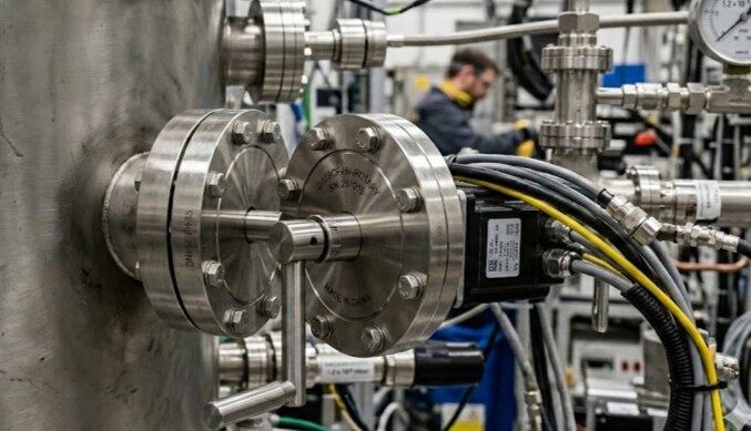
The immediate question becomes how one might deliver external cooling water into this perfectly sealed vacuum without compromising the absolute isolation of the chamber. The solution to this formidable physical barrier is a marvel of modern engineering known as the fluid feedthrough. Far from being a simple plumbing fixture or standard piping, a fluid feedthrough operates as a precision pipeline hub engineered specifically for extreme environments. It serves as the vital, unyielding conduit that bridges the turbulent atmospheric world with the silent vacuum void, allowing the highly controlled transfer of cooling liquids, cryogenic fluids, or high-purity process gases. All of this is achieved while maintaining an impenetrable hermetic seal against immense pressure differentials, ensuring the integrity of both the fluid being delivered and the vacuum environment it penetrates.
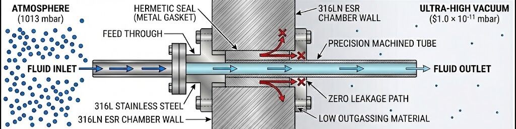
At its core engineering definition, a fluid feedthrough is a highly specialized mechanical interface designed to transmit fluids into high vacuum, ultra-high vacuum, or pressurized systems through a flawless hermetic seal. While a casual observer might liken it to a standard water pipe, the reality is far more complex. It consists of meticulously machined hollow metal tubes that physically penetrate the thick, unyielding metallic walls of a vacuum vessel.
The primary challenge governing the design of these devices is not merely the physical transportation of matter. The feedthrough must facilitate a smooth, uninterrupted flow of fluids while simultaneously resisting massive internal and external pressure differentials. On the atmospheric side of the feedthrough, the environment sits at standard atmospheric pressure. On the vacuum side, the pressure may drop exponentially to regimes as low as 1.0 × 10⁻¹¹ millibars. To put this into perspective, the feedthrough must guarantee absolute hermeticity, ensuring that not a single drop of cooling liquid leaks and not a single molecule of external atmospheric gas permeates the vacuum chamber.
Furthermore, the materials selected for these pipeline hubs must exhibit exceptional purity and low outgassing properties. Austenitic stainless steels, specifically grades like 304, 316L, and highly purified 316LN electroslag remelted steel, are utilized to ensure that the metals themselves do not release trapped gases into the ultra-high vacuum environment. This absolute isolation ensures that energy, matter, and mechanical motion can pass through the vessel wall without degrading the highly sensitive internal atmosphere.
The physics of thermal dynamics rely on three primary mechanisms to transfer heat from one physical system to another. These mechanisms are thermal conduction, thermal convection, and thermal radiation. In standard environments, convection—the bulk movement of fluids such as air or water—acts as the dominant and most efficient cooling mechanism. Heated air expands, becomes less dense, and rises, creating circulation currents that continuously transport energy away from a heat source. However, inside a vacuum chamber, the complete absence of a fluid medium entirely eliminates convective heat transfer. Equipment must therefore be cooled through thermal radiation or direct physical contact, governed strictly by Fourier's law of thermal conduction. According to the second law of thermodynamics, this spontaneous heat transfer must occur from a region of high temperature to a region of lower temperature.
Fluid feedthroughs act as the indispensable vacuum air conditioning system by enabling this direct physical cooling. General service fluid feedthroughs circulate chilled water through single-walled tubes to extract heat from internal components via direct conduction. However, certain advanced applications—such as high-energy particle accelerators, deep-space simulators, or specialized quantum sensor calibrations—require extreme cryogenic cooling using Liquid Nitrogen at a temperature of -196°C or 77K.
Pumping a cryogenic fluid through a highly conductive metal boundary that separates room-temperature air from a high vacuum presents severe thermodynamic hazards. If a standard single-wall pipe were utilized for this task, the extreme thermal gradient would cause the atmospheric side of the mounting flange to freeze almost instantly. This would lead to rapid condensation and a heavy, destructive buildup of ice. Such frost accumulation could compromise the delicate elastomer or metal vacuum seals, clog the atmospheric piping, and allow the machinery being served to heat up unchecked. In the worst-case scenario, the thermal shock could result in a catastrophic, uncontrolled release of rapidly expanding nitrogen gas.
To definitively solve this thermodynamic crisis, cryogenic fluid feedthroughs utilize a highly sophisticated dual-wall coaxial tube construction. An inner tube safely carries the cryogenic fluid, while an outer support tube is concentrically welded to the vacuum mount. The physical gap between these two concentric tubes is left entirely open to the vacuum chamber, creating an internal vacuum cavity. Because a vacuum is a nearly perfect insulator against conduction and convection, this coaxial cavity acts as an exceptional thermal barrier. This intricate design drastically reduces heat transfer, ensuring the cooling fluid reaches the internal target at -196°C while the external atmospheric flange remains safe, at room temperature, and completely ice-free.
| Heat Transfer Mode | Physical Mechanism | Effectiveness in Vacuum | Mitigation via Fluid Feedthrough |
|---|---|---|---|
| Convection | Bulk fluid motion carrying thermal energy | Zero. No fluid medium exists to carry heat. | Replaced entirely. |
| Radiation | Electromagnetic wave emission | Low to Moderate. Highly dependent on surface area and emissivity. | Insufficient for high-power electronics. |
| Conduction | Microscopic molecular collisions | High. Requires direct physical contact. | Feedthroughs deliver liquid coolants directly to internal heat sinks. |
Moving beyond temperature mitigation, fluid feedthroughs are completely indispensable in the high-tech realm of semiconductor manufacturing, acting as precision gas bartenders. In critical fabrication processes such as Plasma-Enhanced Chemical Vapor Deposition and Reactive Ion Etching, the vacuum chamber is not maintained as an entirely empty void. Instead, it requires the meticulous, highly controlled injection of extremely pure process gases to manipulate materials at the atomic level.
Through specialized fluid feedthroughs, inert carrier gases such as Argon and highly reactive gases including Sulfur Hexafluoride, Tetrafluoromethane, and pure Oxygen are delivered directly into the deposition or etching zones. The feedthrough must interface flawlessly with external Mass Flow Controllers and complex bubbler systems. These bubbler systems maintain liquid or solid precursors in a temperature-controlled bath, allowing a carrier gas to form small bubbles that absorb the precursor vapor before being delivered through the feedthrough into the process chamber.
Once these precisely measured gases are injected into the low-pressure vacuum environment, Radio Frequency or direct current energy is applied. This energy strips electrons from their atomic nuclei, igniting the stable gas into a highly energetic plasma—widely considered the fourth state of matter. This highly reactive mixture of positively charged ions and free electrons is then utilized to selectively etch intricate nanoscale patterns into silicon wafers or to deposit ultra-thin insulating films like Silicon Nitride.
The margin for error in these processes is virtually non-existent. As semiconductor nodes shrink to 5 nanometers and below, their sensitivity to microscopic contamination increases exponentially. If the fluid feedthrough were to suffer even a microscopic leak, trace amounts of oxygen or moisture from the external atmosphere would penetrate the chamber. This intrusion would instantly alter the delicate plasma chemistry, degrading the film composition and irreparably destroying the multi-million-dollar semiconductor yield. Thus, the fluid feedthrough acts as the absolute guarantor of chemical purity.
| Gas Type | Chemical Formula | Primary Function in Semiconductor Processing |
|---|---|---|
| Argon | Ar | Inert carrier gas used to purge chambers and stabilize plasma during physical sputtering. |
| Oxygen | O2 | Frequently mixed with fluorocarbons to enhance etching rates or strip away organic photoresists. |
| Sulfur Hexafluoride | SF6 | Highly reactive gas used extensively in Reactive Ion Etching to aggressively remove silicon and refractory metals. |
| Tetrafluoromethane | CF4 | Combined with oxygen or nitrogen to precisely etch Silicon Nitride and other dielectric thin films. |
The operational integrity of a fluid feedthrough relies entirely on the perfection of its sealing mechanisms. The boundary separating atmospheric pressure from an ultra-high vacuum is constantly subjected to immense mechanical stress, thermal shock, and chemical degradation. Depending on the required vacuum level and extreme thermal demands, engineers deploy specific lines of defense to maintain absolute hermeticity.
The fundamental structural foundation of any high-performance fluid feedthrough is achieved through Tungsten Inert Gas welding or advanced laser welding techniques. The thin-walled stainless steel cooling tubes are permanently fused directly to the heavy mounting flanges, creating a continuous, seamless metallic connection. This rigorous welding process is vital because it completely eliminates trapped macroscopic voids—known in the industry as virtual leaks—and ensures the primary structure is fundamentally impervious to gas permeation.
For high-vacuum applications where internal pressures do not drop below 10-8 millibars, vacuum systems typically utilize ISO-KF or larger ISO-K flanges sealed with precision elastomer O-rings. Made from highly resilient synthetic rubbers such as Viton or Nitrile, these O-rings operate entirely on the principle of elastic deformation. When mechanically clamped between two flat flanges, the rubber is compressed by approximately 20 to 25 percent, forcing the elastomer to flow into and fill the microscopic surface imperfections of the metal faces.
When scientific parameters venture into the demanding Ultra-High Vacuum regimes—pressures below 10-11 millibars—or mandate exposure to extreme temperatures ranging from -270°C to 450°C, standard rubber elastomer seals fail completely. In these extreme frontiers, the industry relies exclusively on the ConFlat flange system, representing a marvel of metallurgical engineering.
A ConFlat flange utilizes a rigorous all-metal sealing mechanism. The mating faces of the stainless steel flanges are precisely machined with exceptionally sharp, circular knife-edges. Sandwiched tightly between these edges is a flat gasket punched from ultra-pure Oxygen-Free High Conductivity copper. As the flange bolts are systematically tightened with high mechanical torque, the significantly harder stainless steel knife-edges violently bite into the softer copper material.
This immense compressive force pushes the copper well beyond its elastic limit and forces it into a state of plastic flow. The displaced copper fills every microscopic imperfection, scratch, and machining groove on the knife-edge. Crucially, as the copper is forced to deform, its internal crystalline lattice undergoes severe work-hardening. This metallurgical phenomenon changes the copper's structure, making it significantly stronger and highly springy.
In scenarios where fluid delivery must be coupled with high-voltage electrical isolation—such as in plasma generation or electron beam equipment—standard all-metal feedthroughs are insufficient. Here, advanced ceramics, primarily high-purity alumina (Al2O3) and sometimes aluminum nitride (AlN), become critical. These technical ceramics provide exceptional dielectric strength, allowing them to isolate thousands of volts (up to 60kV or more) while maintaining mechanical robustness and ultra-high vacuum hermeticity. To integrate these ceramics with stainless steel flanges, engineers employ sophisticated ceramic-to-metal brazing techniques. The ceramic surface is metallized and then brazed using alloys like silver or copper in a vacuum furnace, creating a leak-proof, zero-clearance joint that can withstand extreme thermal gradients and corrosive process gases without degrading.
| Specification | ISO-KF / NW Flanges | ISO-K / ISO-F Flanges | CF / ConFlat Flanges |
|---|---|---|---|
| Primary Seal Material | Elastomer O-Ring | Elastomer O-Ring | Oxygen-Free High Conductivity Copper |
| Physical Sealing Mechanism | Elastic Deformation | Elastic Deformation | Plastic Flow & Work-Hardening |
| Maximum Vacuum Range | > 10-8 mbar | > 10-8 mbar | > 10-11 to 10-13 mbar |
| Maximum Leakage Rate | < 1.0 × 10⁻⁹ mbar l/s | < 1.0 × 10⁻⁹ mbar l/s | < 1.0 × 10⁻¹¹ mbar l/s |
| Operating Temperature Range | -20°C to 200°C | -20°C to 200°C | -270°C to 450°C |
| Component Reusability | Highly reusable | Highly reusable | Single-use only |
Why is it impossible to use ordinary rubber O-rings to seal fluid feedthroughs in extreme temperature environments?
Rubber elastomers operate strictly within the boundaries of their elastic limits. In extremely cold environments—such as the introduction of -196°C liquid nitrogen—the elastomer temperature drops rapidly below its critical glass transition temperature. When this occurs, the rubber entirely loses its molecular elasticity, becoming brittle and glass-like. Any slight vibration or pressure shift will shatter the seal, causing catastrophic fluid leakage. Conversely, under extreme heat—such as a 450°C ultra-high vacuum bake-out—rubber undergoes severe thermal degradation, melting, or shrinking. Furthermore, heated elastomers violently outgas volatile compounds, destroying the purity of the vacuum. Therefore, only plastically deformed, work-hardened metal seals like copper can dynamically absorb and withstand these profound thermal stresses.
How are fluid feedthroughs tested to ensure absolute vacuum integrity?
Before installation, high-performance feedthroughs undergo rigorous helium leak testing. Because helium atoms are exceptionally small and inert, they can penetrate microscopic structural flaws that other gases cannot. A Mass Spectrometer Leak Detector is used to measure any trace helium passing through the seal, ensuring leak rates are well below standard limits like 1.0 × 10⁻¹¹ mbar l/s.
What are the common failure modes of fluid feedthroughs, and how can they be prevented?
Feedthroughs typically fail due to thermal shock, mechanical stress, or seal degradation. For elastomer seals, failure often results from high-temperature baking causing the rubber to outgas and crack. For metal seals, improper bolt torqueing or scratching the knife-edge can compromise the vacuum. Preventive maintenance involves strictly adhering to operating temperature limits, using proper tightening protocols, and routinely inspecting the system for micro-leaks or fluid contamination.